Is an open standard
Supports the entire software development lifecycle
Supports diverse applications areas
Is based on experience and needs of the user community
Supported by many tools
- Rational Software Corporation
- IBM
- Hewlett-Packard
- I-Logix
- ICON Computing
- Intellicorp
- MCI Systemhouse
- Microsoft
- ObjecTime
- Oracle
- Platinum Technology
- Taskon
- Texas Instruments/Sterling Software
- Unisys
The UML is a language for
- visualizing
- specifying
- constructing
- documenting
the artifacts of a software-intensive system
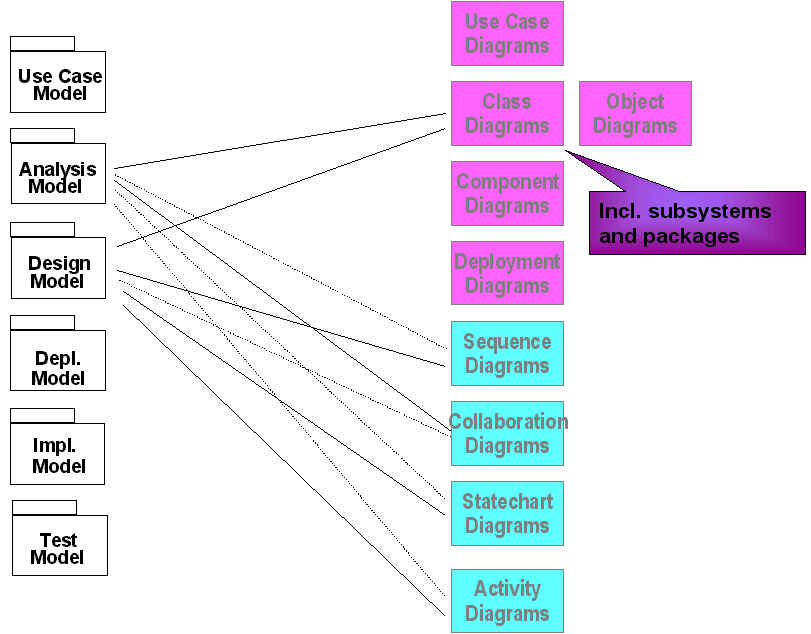
A system is described in several different model types:
- Analysis model describes the functional requirements and the modeling of real-world classes.
- The design transforms the analysis result into a technical solution in terms of a complete working software design.
- The implementation model implements the system by coding it in an OO Programming language.
- The deployment model places the program constructed in a physical architecture with computers and devices.
- Modeling elements
- Relationships
- Extensibility Mechanisms
- Diagrams
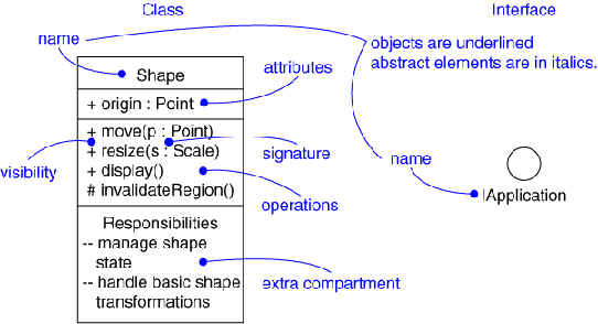
Structural elements
- class, interface, collaboration, use case, active class, component, node
Behavioral elements
- interaction, state machine
Grouping elements
- package, subsystem
Other elements
- note
Dependency
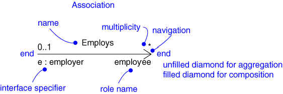
Association
Generalization
Realization
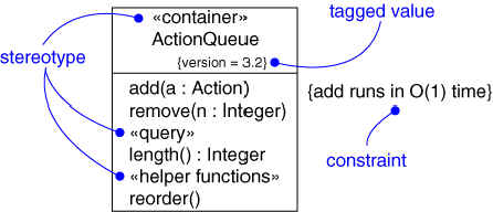
Stereotype
Tagged value
Constraint
A diagram is a view into a model
- Presented from the aspect of a particular stakeholder
- Provides a partial representation of the system
- Is semantically consistent with other views
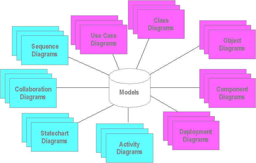
In the UML, there are nine standard diagrams
- Static views: use case, class, object, component, deployment
- Dynamic views: sequence, collaboration, statechart, activity
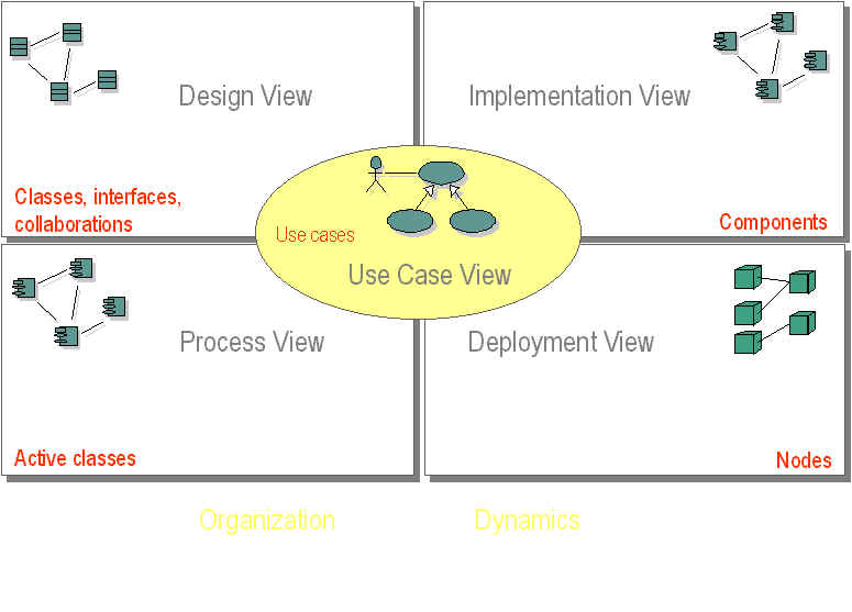
UML organizes a model in a number of views that present different aspects of a system.
Combination of all the views can create a complete picture of a system.
A view is not a graph ; it may contain many diagrams.
- Use-case view: Shows the functionality of the system as perceived by the external user
- Logical view: Shows how functionality is designed inside the system including static structure and dynamic behavior
- Component view: Shows the organization of code components
- Concurrency view: Shows concurrency in the system addressing communication and synchronization challenges within the system
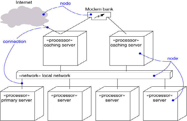
- Deployment view: Shows the deployment of the system into the physical architecture with computers and devices called nodes
The actual graphs that show model element symbols arranged to illustrate a particular part or aspect of the system.
- Use case diagram
- Class diagram
- Object diagram
- State diagram
- Sequence diagram
- Collaboration diagram
- Activity diagram
- Component diagram
- Deployment diagram
Captures system functionality as seen by users
Captures system functionality as seen by users
Built in early stages of development
Purpose
- Specify the context of a system
- Capture the requirements of a system
- Validate a system’s architecture
- Drive implementation and generate test cases
Developed by analysts and domain experts
Captures the vocabulary of a system
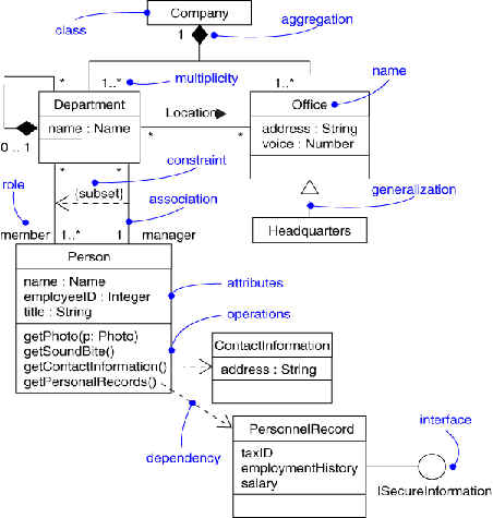
Captures the vocabulary of a system
Built and refined throughout development
Purpose
- Name and model concepts in the system
- Specify collaborations
- Specify logical database schemas
Developed by analysts, designers, and implementers
Captures instances and links
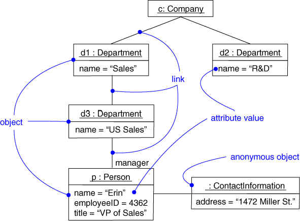
Shows instances and links
Built during analysis and design
Purpose
- Illustrate data/object structures
- Specify snapshots
Developed by analysts, designers, and implementers
Captures the physical structure of the implementation
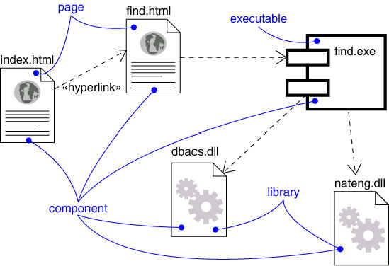
Captures the physical structure of the implementation
Built as part of architectural specification
Purpose
- Organize source code
- Construct an executable release
- Specify a physical database
Developed by architects and programmers
Captures the topology of a system’s hardware
Captures the topology of a system’s hardware
Built as part of architectural specification
Purpose
- Specify the distribution of components
- Identify performance bottlenecks
Developed by architects, networking engineers, and system engineers
Captures dynamic behavior (time-oriented)
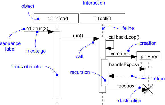
Captures dynamic behavior (time-oriented)
Purpose
- Model flow of control
- Illustrate typical scenarios
Captures dynamic behavior (message-oriented)
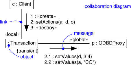
Captures dynamic behavior (message-oriented)
Purpose
- Model flow of control
- Illustrate coordination of object structure and control
Captures dynamic behavior (event-oriented)
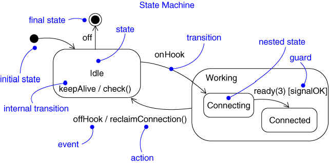
Captures dynamic behavior (event-oriented)
Purpose
- Model object lifecycle
- Model reactive objects (user interfaces, devices, etc.)
Captures dynamic behavior (activity-oriented)
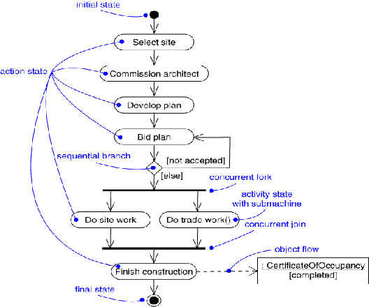
Captures dynamic behavior (activity-oriented)
Purpose
- Model business workflows
- Model operations

Drive a number of development activities
- Creation and validation of the system’s architecture
- Definition of test cases and procedures
- Planning of iterations
- Creation of user documentation
- Deployment of system
Synchronize the content of different models
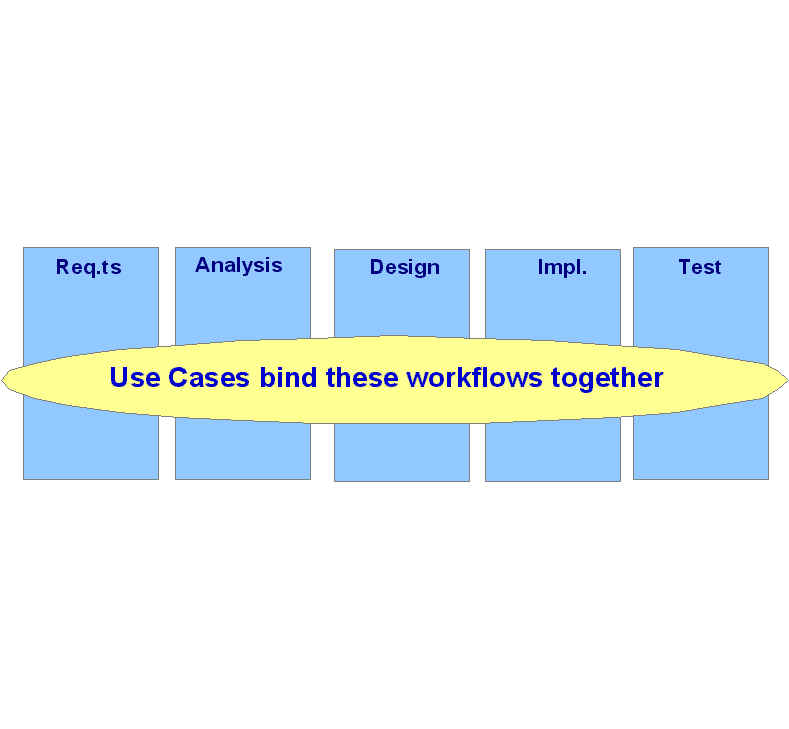
Use-Case Modeling: Introduction
- A use case is a modeling technique used to describe what a new system should do or what an existing system already does.
- Use case modeling was created by Ivar Jacobson based on his experiences developing AXE system at Ericsson, specifically, the OOSE and Objectory methods.
The primary components of a use-case model are
- use cases: A set of sequences of actions a system performs that yield an observable result of value to a particular actor.
- Actor
- System modeled
The functionality is represented by a number of use cases, and each use case specifies a complete functionality.
When the functionality is complete, the use case must handle the entire function, from its initiation by an external actor until it has performed the requested functionality.
A use case must always deliver a value to an actor, the value being whatever the actor wants form the system.
What happens in use cases do not cover the entire system functionality?
To decide and describe the functional requirements of the system.
To give a clear and consistent descriptions of what the system should do.
To provide a basis for performing system tests that verify the system.
To provide the ability to trace functional requirements into actual classes and operations in the system.
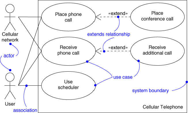
A use-case model is described in UML as a use-case diagram.
A use-case model can be divided into a number of use-case diagrams.
The actual description of the use-case contents is usually given in plain text.
An activity diagram may be used instead of textual description of use case.
An actor is someone or something that interacts with the system
An actor is who or what uses the system.
An actor is a type (a class), not an instance.
An actor represents a role, not an individual user of the system.
One person may have different roles in a system.
An actor communicates with the system by sending and receiving messages.
Principal actors: People who use the main system functions
Secondary actors: People who perform administration or maintenance tasks
External hardware: The unavoidable hardware devices that are part of the application domain and must be used
Other systems: The other systems with which the system must interact.
Who will use the main functionality of the system (primary actors)?
Who will need support from the system to their daily tasks?
Who will need to maintain, administrate, and keep the system working (secondary actors)?
Which hardware devices does the system need to handle?
With which other systems does the system need to interact?
Who or what has an interest in the results (the value) that the system produce?
An actor is a class, and is shown as a class rectangle with the stereotype <<actor>>.
The standard stereotype icon of a stickman is normally shown in use-case diagrams. It has the actor name below the figure.
Since actors are classes, they can have the same relationships as classes.
In use-case diagrams, only generalization relationships are used to describe common behavior between a number of actors.
A use case is always initiated by an actor.
A use case provides value to an actor.
A use case is complete. A use case is not complete until the end-value is produced. Be careful in dividing a use case into smaller use cases.
A use case is a class, not an instance.
A use case describes the functionality as a whole, including possible alternatives, errors, and exceptions that can occur during the execution of the use case.
A scenario is an instantiation of a use case.
A scenario represents an actual usage of the system, a specific execution path through the system.
A scenario instance of the use case "Signing Insurance" could be "John Smith contacts the system by telephone and signs for car insurance for the Ford Escort he just bought.
Which functions does the actor require from the system? What does the actor need to do?
Does the actor need to read, create, destroy, modify or store some kind of information in the system?
Does the actor have to be notified about events in the system, or does the actor need to notify the system about something? What does those events represent in terms of functionality?
Could the actor’s daily work be simplified or made efficient through new functions in the system?
What input/output does the system need? Where does this input/output come from or go to?
What are the major problems with the current implementation of this system (perhaps a manual system instead of an automated one)?
Note: All the material in these UML pages are provided by a student as a research project.